Fill Out Your Electrical Panel Schedule Template
The Electrical Panel Schedule form plays a crucial role in the management and organization of electrical systems within residential and commercial buildings. This form provides a detailed breakdown of the electrical panel's circuits, indicating the specific loads and the corresponding breakers. It serves as a vital reference for electricians, contractors, and building owners, ensuring that everyone involved understands the distribution of electrical power. By clearly listing each circuit's purpose, the form helps in identifying potential overloads and facilitates maintenance and troubleshooting. Additionally, it aids in compliance with safety standards and regulations, making it an essential tool for effective electrical management. Properly completing and maintaining this schedule not only enhances safety but also promotes efficiency in electrical system operations.
Similar forms
The Electrical Load Calculation is a document that outlines the expected electrical load for a specific area or building. Similar to the Electrical Panel Schedule, it provides detailed information about the electrical requirements. Both documents help ensure that the electrical system can handle the demand placed upon it. The Load Calculation considers factors such as lighting, appliances, and equipment, while the Panel Schedule organizes the distribution of circuits and breakers within the panel itself.
The Arizona Transfer-on-Death Deed form allows property owners to designate beneficiaries who will receive their property upon their passing, without the need for probate. This legal document can simplify the transfer of property and provide clarity for heirs, ensuring that assets are distributed according to the owner's wishes. To start the process of securing your property for future beneficiaries, consider visiting https://arizonaformpdf.com/ for the necessary forms.
The Circuit Directory serves as a companion document to the Electrical Panel Schedule. It lists the circuits within the electrical panel and identifies what each circuit powers. This document is essential for maintenance and troubleshooting, just as the Panel Schedule is crucial for understanding how power is distributed. Both documents work together to provide a comprehensive overview of the electrical system's layout and functionality.
The One-Line Diagram visually represents the electrical system's components and their connections. Like the Electrical Panel Schedule, it is used for planning and maintenance purposes. The One-Line Diagram simplifies complex electrical systems into a single line that shows how power flows through the system. This visual aid complements the detailed information found in the Panel Schedule, helping electricians and engineers understand the overall design.
The Service Entrance Schedule outlines the main service equipment and its specifications. Similar to the Electrical Panel Schedule, it details the capacity and ratings of the electrical service. This document is crucial for determining whether the existing service can support additional loads. Both documents ensure that the electrical system is appropriately sized and safe for use.
The Equipment Schedule lists all major electrical equipment, including transformers, generators, and switchgear. This document is similar to the Electrical Panel Schedule in that it provides essential details about each piece of equipment, such as ratings and locations. Both schedules serve to ensure that all components of the electrical system are accounted for and properly maintained.
The Wiring Diagram illustrates the specific wiring connections and configurations within an electrical system. Like the Electrical Panel Schedule, it is essential for installation and troubleshooting. The Wiring Diagram provides detailed information on how circuits are connected, while the Panel Schedule focuses on the organization of those circuits within the electrical panel. Together, they provide a complete picture of the electrical system’s structure and function.
Form Specifications
| Fact Name | Description |
|---|---|
| Purpose | The Electrical Panel Schedule form is used to document the circuit allocation and load distribution in an electrical panel. |
| Components | This form typically includes information such as circuit numbers, load capacities, and types of breakers. |
| Regulatory Compliance | Many states require the use of an Electrical Panel Schedule to comply with local electrical codes and safety regulations. |
| State-Specific Forms | Some states have their own versions of the Electrical Panel Schedule form, governed by state electrical codes. |
| Load Calculation | Accurate load calculations are essential to prevent overloading circuits, which can lead to safety hazards. |
| Installation Documentation | The form serves as a vital part of installation documentation, aiding in future maintenance and inspections. |
| Updates and Modifications | Any changes to the electrical system should be reflected in the Electrical Panel Schedule to ensure ongoing compliance and safety. |
Different PDF Templates
Batting Line Up Strategy - Record GM for both teams to track communications.
Return to Work Doctors Note - Use this document to apply for a work release program during incarceration.
For individuals looking to support a colleague's application, completing the structured Recommendation Letter form required for candidate endorsement can significantly influence chances of success. This form facilitates clear communication of the individual’s skills and accomplishments, essential for any admissions or job application process.
Irs Form 1099 Nec - Accurate reporting helps maintain compliance with federal tax regulations.
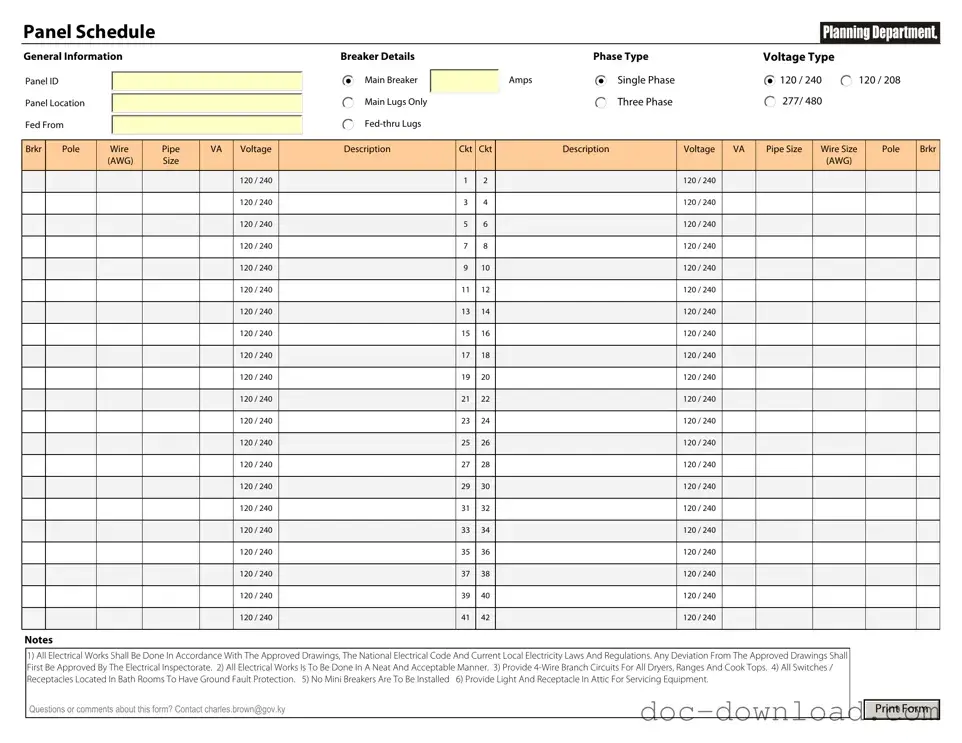
Sample - Electrical Panel Schedule Form
Panel Schedule
General Information
Panel ID
Panel Location
Fed From
Breaker Details
Main Breaker
Main Lugs Only
|
Phase Type |
Voltage Type |
|
Amps |
Single Phase |
120 / 240 |
120 / 208 |
|
Three Phase |
277/ 480 |
120 / 240 |
|
|
|
Brkr |
Pole |
Wire |
Pipe |
VA |
Voltage |
Description |
Ckt |
Ckt |
Description |
Voltage |
VA |
Pipe Size |
Wire Size |
Pole |
Brkr |
|
|
(AWG) |
Size |
|
|
|
|
|
|
|
|
|
(AWG) |
|
|
|
|
|
|
|
|
|
|
|
|
|
|
|
|
|
|
|
|
|
|
|
120 / 240 |
|
1 |
2 |
|
120 / 240 |
|
|
|
|
|
|
|
|
|
|
|
|
|
|
|
|
|
|
|
|
|
|
|
|
|
|
120 / 240 |
|
3 |
4 |
|
120 / 240 |
|
|
|
|
|
|
|
|
|
|
|
|
|
|
|
|
|
|
|
|
|
|
|
|
|
|
120 / 240 |
|
5 |
6 |
|
120 / 240 |
|
|
|
|
|
|
|
|
|
|
|
|
|
|
|
|
|
|
|
|
|
|
|
|
|
|
120 / 240 |
|
7 |
8 |
|
120 / 240 |
|
|
|
|
|
|
|
|
|
|
|
|
|
|
|
|
|
|
|
|
|
|
|
|
|
|
120 / 240 |
|
9 |
10 |
|
120 / 240 |
|
|
|
|
|
|
|
|
|
|
|
|
|
|
|
|
|
|
|
|
|
|
|
|
|
|
120 / 240 |
|
11 |
12 |
|
120 / 240 |
|
|
|
|
|
|
|
|
|
|
|
|
|
|
|
|
|
|
|
|
|
|
|
|
|
|
120 / 240 |
|
13 |
14 |
|
120 / 240 |
|
|
|
|
|
|
|
|
|
|
|
|
|
|
|
|
|
|
|
|
|
|
|
|
|
|
120 / 240 |
|
15 |
16 |
|
120 / 240 |
|
|
|
|
|
|
|
|
|
|
|
|
|
|
|
|
|
|
|
|
|
|
|
|
|
|
120 / 240 |
|
17 |
18 |
|
120 / 240 |
|
|
|
|
|
|
|
|
|
|
|
|
|
|
|
|
|
|
|
|
|
|
|
|
|
|
120 / 240 |
|
19 |
20 |
|
120 / 240 |
|
|
|
|
|
|
|
|
|
|
|
|
|
|
|
|
|
|
|
|
|
|
|
|
|
|
120 / 240 |
|
21 |
22 |
|
120 / 240 |
|
|
|
|
|
|
|
|
|
|
|
|
|
|
|
|
|
|
|
|
|
|
|
|
|
|
120 / 240 |
|
23 |
24 |
|
120 / 240 |
|
|
|
|
|
|
|
|
|
|
|
|
|
|
|
|
|
|
|
|
|
|
|
|
|
|
120 / 240 |
|
25 |
26 |
|
120 / 240 |
|
|
|
|
|
|
|
|
|
|
|
|
|
|
|
|
|
|
|
|
|
|
|
|
|
|
120 / 240 |
|
27 |
28 |
|
120 / 240 |
|
|
|
|
|
|
|
|
|
|
|
|
|
|
|
|
|
|
|
|
|
|
|
|
|
|
120 / 240 |
|
29 |
30 |
|
120 / 240 |
|
|
|
|
|
|
|
|
|
|
|
|
|
|
|
|
|
|
|
|
|
|
|
|
|
|
120 / 240 |
|
31 |
32 |
|
120 / 240 |
|
|
|
|
|
|
|
|
|
|
|
|
|
|
|
|
|
|
|
|
|
|
|
|
|
|
120 / 240 |
|
33 |
34 |
|
120 / 240 |
|
|
|
|
|
|
|
|
|
|
|
|
|
|
|
|
|
|
|
|
|
|
|
|
|
|
120 / 240 |
|
35 |
36 |
|
120 / 240 |
|
|
|
|
|
|
|
|
|
|
|
|
|
|
|
|
|
|
|
|
|
|
|
|
|
|
120 / 240 |
|
37 |
38 |
|
120 / 240 |
|
|
|
|
|
|
|
|
|
|
|
|
|
|
|
|
|
|
|
|
|
|
|
|
|
|
120 / 240 |
|
39 |
40 |
|
120 / 240 |
|
|
|
|
|
|
|
|
|
|
|
|
|
|
|
|
|
|
|
|
|
|
|
|
|
|
120 / 240 |
|
41 |
42 |
|
120 / 240 |
|
|
|
|
|
|
|
|
|
|
|
|
|
|
|
|
|
|
|
|
|
Notes
1)All Electrical Works Shall Be Done In Accordance With The Approved Drawings, The National Electrical Code And Current Local Electricity Laws And Regulations. Any Deviation From The Approved Drawings Shall First Be Approved By The Electrical Inspectorate. 2) All Electrical Works Is To Be Done In A Neat And Acceptable Manner. 3) Provide
Receptacles Located In Bath Rooms To Have Ground Fault Protection. 5) No Mini Breakers Are To Be Installed 6) Provide Light And Receptacle In Attic For Servicing Equipment.
Questions or comments about this form? Contact charles.brown@gov.ky
Print Form